X58 for the Masses: Gigabyte's EX58-UD3R & EX58-UD4P
|
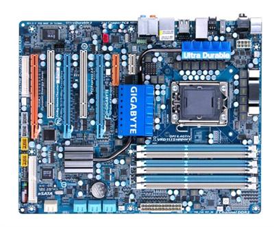
The EX58-UD4P is similar to the UD3R in many respects, but does have a few welcome additions. LEDs placed around the board display the current load on the CPU and other components with the higher number of LEDs lit equating to the heavier the load conditions. Whereas the UD3R only displays the load on the CPU (seen in the upper most corner by the DIMM slots), the UD4P has LEDs for not only the CPU load, but the memory as well, with individual voltages and temperature readouts for each. Of course, having all of these LEDs is only helpful when one either has their case open, or has a windowed side panel, which diminishes their value a little bit. The UD4P also has a couple of additional power-user niceties such as power and reset buttons directly on the board near the DIMM slots (once again) and a clear CMOS button that can be found on the back, making overclocking missteps a little less of a headache.
The heatsinks are secured from the underside of the board for both the NorthBridge and SouthBridge on the UD4P, yet only the NorthBridge in the UD3R. All of the heatsinks on both the UD3R and UD4P are passive, meaning users will need proper airflow, but the upside is they also do not create any extra noise output. And all of these heatsinks are relatively low-profile, preventing conflicts with other components or cables. A single heatpipe leads from the South Bridge to the heatsink placed over the NorthBridge on the UD4P model, but is curiously missing from the UD3R. From there, another pipe presumably conducts heat away from this area to another aluminum heatsink placed on top of the MOSFETs in the VRM.
Power and reset buttons are placed nearby the DIMM slots, and are mostly useful during initial build testing or overclocking, as afterwards you probably won't be sticking your hands into the chassis just to power up your system. Six DDR3 slots support up to 24GB of memory. Three full-length PCI-E slots allow for up to three add-in graphics cards to be installed, albeit in a 16X, 16X, 8X configuration, and there is another smaller PCI-E X1 slot good for upgrading your audio to a third-party card such as Creative's X-Fi Titanium.
Both boards utilize front-angled SATA ports - 6 coming from the ICH10/R and an additional two ports supported by the nearby Gigabyte SATA2 chip. We also noticed a few solder points between these connectors where even more ports could have been installed using another controller from JMicron, as found on the higher-end EX58-UD5 and EX58-EXTREME. Front panel pins are bracketed within a plastic placeholder and thankfully the pin assignments are printed directly nearby. USB and IEEE-1394 headers are placed nearby along the edge of the board, 2 Firewire connectors on the UD4P and one on the UD3R. Each board comes with a floppy drive port put high in the far corner, yet very close to the final slot which may hinder installations one way or the other.
Audio chips also differ slightly. While Realtek provides both chips, the UD3R ships with the ALC888 CODEC and the UD4P gets the upgraded ALC889a, which has a significantly better signal-to-noise ratio and supports Realtek's proprietary loss-less content protection technology that protects pre-recorded content while still allowing full-rate audio enjoyment from DVD audio, Blue-ray DVD, or HD DVD discs. The rear output offers similar options, although the configuration of which differs a bit. The major difference between the two stems from the addition of the Clr CMOS button on the UD4P.


