ASUS Z170 ROG Maximus VIII Extreme Motherboard Review: An Impressive Platform For Skylake
The black PCB is complimented by greyish-platinum heatsinks and shielding with ruby red accents. It may not be as glitzy as some past ROG products. But what it may lack for some in terms of aesthetic appeal, it wholly makes up for in features.
At the top of the image above, the aforementioned shield are visible. They cover the Exteme Engine Digi+ MOSFET array, chokes and some of the board’s 10K black metallic capacitors. More can be seen outlining the Intel LGA 1151 socket. Also at the very top left we have a pair of EATX 12v power connectors (4- and 8-pin). Moving over to the right a few inches, we see a CPU fan header. To the right of this are the 4-DIMM slots which support high speed DDR4 memory. The upper right is home to another CPU fan header and a CPU water pump connector. Just below this we see the motherboards integrated Start and Reset buttons. Next to these is the Q-code LED readout to help troubleshoot any errors that may crop up when booting or during the POST.
At the right along the edge of the board are the Safe Boot, Clear CMOS and MemOK buttons. Safe Boot functions the same as on the OC Panel II. After a failed OC, pressing this will take the user into the BIOS Safe Mode while retaining OC settings so users may fine tune them accordingly. The MemOK switch automatically attempts to optimize installed memory for successful booting. The 24-pin ATX power connector appears just below.
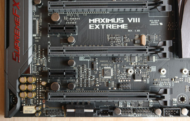
Along the bottom of the board, moving from right to left we see the front panel connectors for system power, reset, HDD LED etc. Next is another pair of additional fan headers, a sensor header for system monitoring and the BIOS switch to toggle between the dual BIOS options. Above this are the BIOS eproms, some indicator LEDs, and above those is a single M.2 SATA connector. Next up is the SLI/CFX switch to engage the PCIe LEDs for GPU installation recommendations, then another fan header, followed by a couple of USB 2.0 headers.
Next we have the ROG EXT header to connect the OC Panel II we showed you on the first page and a 4-pin EX Plug (molex) for added power when using multi-GPU setups. At the far left is the board's front panel audio connector. Traveling upward along the left edge, is the SupremeFX 2015 onboard audio codec components, much of which are hidden beneath the SupremeFX-labeled shielding. This includes, the ten DAC 7.1 audio processor, Nichicon capacitors, onboard headphone amp supporting 32-600 ohms headphones.
Finally let's take a peek at the rear panel and connectivity options. From left to right we see the Clear CMOS button to reset the BIOS to default settings, as well as the USB BIOS Flashback button. Then we have a column of USB ports. The top two are ASmedia controlled USB 3.0 ports featuring USB 3.1 boost and AI Charger+ support to charge supported devices even when the system is powered down. The bottom two ports are ASmedia controlled USB 3.1 ports, that also feature charging and boost functionality. Next is the Wi-Fi Go module to connect the Wi-Fi adapter. alongside the board's DisplayPort and HDMI ports. Next in line is the RJ-45 LAN port atop an Intel controlled USB 3.1 Type-A port, which sits above an Intel-powered USB 3.1 Type-C port. To the right is the PS/2 keyboard/mouse connector, which sits just above another pair of Intel USB 3.0 ports (lower port also used for BIOS Flashback). Pulling up the rear are the audio ports (mic & speaker jacks) and Optical S/PDIF out port.


