X58 for the Masses: Gigabyte's EX58-UD3R & EX58-UD4P

Many positive commentaries have been written about Intel's current flagship Core i7 processors and its companion X58 Express chipset, due to the solid performance gains offered by the platform. In addition to the increased performance offered by Core i7 processors though, the X58 chipset also brings with it native support for ATI CrossFireX and NVIDIA SLI multi-GPU technologies--provided support is available in the BIOS--as well as support for the flexible triple channel memory controller integrated into the Core i7. What might be concerning for some, however, is the overall cost of putting together all of the components we just mentioned. Currently, the cheapest Core i7 out there, the 920, will run you about $280, which is a huge savings over the 940 at about double that price and the Extreme Edition 965 at a cool $1K. DDR3 memory has really come down in price, thankfully, so picking up a three sticks of RAM is certainly not as pricey as it may have been when the Core i7 launched. And obviously graphics cards pricing is all over the map these days.
But, it all starts with the motherboard and most of the X58-based offerings out there are not cheap. Simply put, being the latest and greatest always commands a premium and it doesn't help when there's no real competition (on the chipset level at least) to help keep prices in check. Thus, we were very eager to test a couple of Gigabyte's latest X58 Express based motherboards that are priced much more competitively than many of the other X58 boards currently on the market. Gigabyte may have sacrificed a little here or there to get to a lower price point, but with the five X58-based boards they have in their line-up currently, there should be a board to fit just about everyone's needs.
Are these new motherboards still worth the investment versus competitive offerings? That's what we're here to find out...

|
| Processor Support Support for an Intel® Core™ i7 series processor in the LGA 1366 package L3 cache varies with CPU Chipset North Bridge: Intel® X58 Express Chipset South Bridge: Intel® ICH10R Memory 4x 1.5V DDR3 DIMM sockets supporting up to 16 GB of system memory (UD4P has 6x for 24MB) Dual/3 channel memory architecture Support for DDR3 2000+/1333/1066/800 MHz memory modules Expansion Slots 2x PCI Express x16 slots, running at x16 (PCIEX16_1/PCIEX16_2) * 1x PCI Express x8 slot, running at x8 (PCIEX8_1) (UD4P ONLY) 1x PCI Express x4 slot 1x PCI Express x1 slot 2x PCI slots Storage I/O ICH10/R South Bridge: 6x SATA 3Gb/s connectors (SATA2_0, SATA2_1, SATA2_2, SATA2_3, SATA2_4, SATA2_5) supporting up to 6 SATA 3Gb/s devices Support for SATA RAID 0, RAID 1, RAID 5, and RAID 10 GIGABYTE SATA2 chip: iTE IT8720 chip: Support NVIDIA 3-Way SLI™ / ATI CrossFireX™ Technology (ATI CrossFire only on UD3R) Audio Realtek ALC888 codec (UD4P uses ALC889A) High Definition Audio 2/4/5.1/7.1-channel * Support for Dolby® Home Theater (UD4P ONLY) Support for S/PDIF In/Out Support for CD-In Sound Blaster X-Fi MB utility (30-day trial version) LAN Realtek 8111D chip (10/100/1000 Mbit) IEEE-1394 T.I. TSB43AB23 chip Up to 3 IEEE 1394a ports (1 on the back panel, 2 via the IEEE 1394a brackets connected to the internal IEEE 1394a headers) USB Integrated in the South Bridge Up to 12 USB 2.0/1.1 ports (8 on the back panel, 4 via the USB brackets connected to the internal USB headers) |
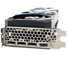
Back Panel I/O Ports 1x PS/2 keyboard port 1x PS/2 mouse port 1x coaxial S/PDIF Out connector 1x optical S/PDIF Out connector 2x IEEE 1394a port (1 on UD4P) *1x clearing CMOS switch (UD4P ONLY) 8x USB 2.0/1.1 ports 1x RJ-45 port 6x audio jacks (Center/Subwoofer Speaker Out/Rear Speaker Out/Side Speaker Out/Line In/Line Out/Microphone) Internal I/O Connectors 1x 24-pin ATX main power connector 1x 8-pin ATX 12V power connector 1x floppy disk drive connector 1x IDE connector 8x SATA 3Gb/s connectors 1x CPU fan header 3x system fan headers 1x power fan header 1x North Bridge fan header 1x front panel header 1x front panel audio header 1x CD In connector 1x S/PDIF In header 1x S/PDIF Out header 2x USB 2.0/1.1 headers 1x IEEE 1394a headers (UD4P has 2) 1x power LED header 1x chassis intrusion header 1x serial port header (UD3R ONLY) 1x clearing CMOS jumper (UD3R) power and reset switch ONLY on UD4P BIOS 2x 8 Mbit flash Use of licensed AWARD BIOS Support for DualBIOS™ PnP 1.0a, DMI 2.0, SM BIOS 2.4, ACPI 1.0b Special Features Support for @BIOS Support for Q-Flash Support for Virtual Dual BIOS Support for Download Center Support for Xpress Install Support for Xpress Recovery2 Support for EasyTune (Note 6) Support for Dynamic Energy Saver Advanced Support for Time Repair Support for Q-Share H/W Monitoring System voltage detection CPU/System/North Bridge temperature detection CPU/System/Power fan speed detection CPU overheating warning CPU/System/Power fan fail warning CPU/System fan speed control Form Factor ATX Form Factor 12 inch x 9.6 inch ( 30.5 cm x 24.4 cm ) |
;) |
;) |
|
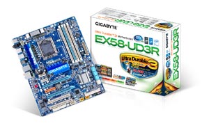
GIGABYTE EX58-UD3R |
GIGABYTE EX58-UD4P |
;) |
;) |
Looking at both accessory bundles, we see that both packages contains a driver disk, user's manual, quick installation guide, single IDE and floppy cables, four SATA cables and the rear I/O shield. It's a completely spartan list of accessories fit for more affordable priced boards. At a minor step up, the UD4P comes with all of the above, but also includes an eSATA case bracket, one 2-port IEEE-1394a bracket, and 2-way and 3-way SLI bridges. Of course, saving on accessories means bringing the total cost of the package lower in order to hit certain price points in the market.


;)