MSI P35 Platinum Motherboard
MSI P35 Platinum Features and Layout
Probably the first thing one notices when looking at the MSI P35 Platinum is the board’s unique heat pipe design. In what can most easily be described as a ‘roller coaster’ heat pipe implementation, the board has a single heat pipe that connects the south bridge, north bridge, and CPU / memory voltage regulators, passively cooling all three.
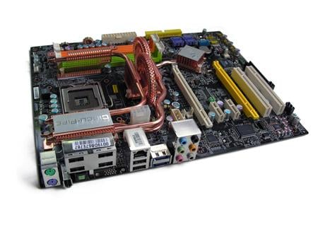
The P35 Platinum uses the same black PCB that MSI has used in recent mid-ranged motherboards including the MSI 965 Platinum and MSI K9N Platinum. The board itself didn’t have any obvious design flaws and working with it yielded no serious problems.
![]()

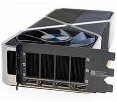
The board’s roller coaster heat pipe isn’t the only new and unique feature the P35 brings to the table. MSI has also decided to drop most legacy I/O ports (leaving the PS/2 keyboard and mouse inputs). Dropping serial and Parallel ports frees up enough real estate to offer a total of six USB 2.0 ports on the back panel. Notice how four of the six USB 2.0 ports are spaced out between each other, this is to accommodate multiple USB memory sticks and devices that take up more room than standard USB devices, like some oversized flash drives. The P35 Platinum also has 5.1 audio inputs, a firewire port, an optical PSDIF port, and two eSATA ports on the back I/O panel.
;)
;)
;)
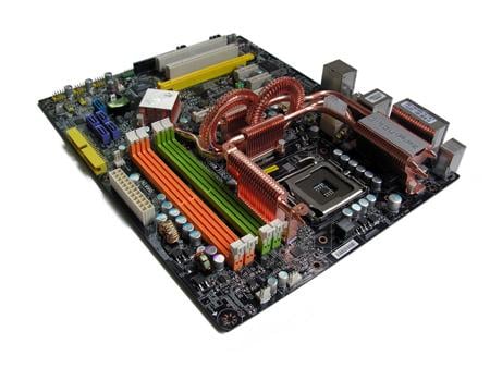
The P35 Platinum’s heat pipe design is reminiscent of the ASUS A8N SLI Premium released a few years back, but taken to the next level. The P35 Platinum’s heat pipe did an excellent job of dissipating heat and was never at a point where it was too hot too touch during the review process. It’s refreshing to see a motherboard manufacturer put extra time and effort into designing a solution that can cool not only the board’s south and north bridges, but also its voltage regulators, as they can get extremely hot and cause instability when overclocking.
;)
;)
;)
The board’s 8 pin power connector has an extension already attached which thankfully makes connecting the cable inbetween the heat-pipe jungle an easy task. Here we can also see the molex PCI Express power connector and the two four pin case fan power headers. The board is complete with two PCIE 16X slots, but if both have cards in them at the same time, one is limited to only 4X speeds while the other keeps 16X. It’s also nice to see that the board still features regular PCI slots, as many people still have PCI devices they want to use in their new systems.
;)
;)
;)
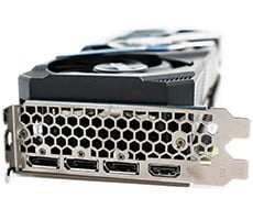
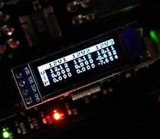
The red button featured above (right-most image) is a CMOS reset button, allowing you to reset your system back to normal after those frequent failed overclocking attempts. Directly to the right of the CMOS reset button is MSI’s new LED based debug system. Although it is nicer than MSI’s traditional D-bracket debug system that needed to be housed in a PCI slot, we encountered some problems with the system while working with the board. One was during a botched heatsink install that didn’t make correct contact with the X6800 CPU and therefore the CPU reached its top internal temperature and shut down. During this, the debug codes kept saying it was a memory problem, so I kept switching memory out over and over again to see if the board was highly incompatible with the high end memory on the market. I also had a problem with the diagnostic LED’s being so bright that actually figuring out the sequence of colors in the debug system required some additional work.