|

 |
|
Quality and Setup of the Iwill P4ES |
| IDE,
SATA, USB, and some other acronyms on board |
|
Perhaps not as glitzy as
some of the other motherboards we have reviewed
lately, the P4ES makes up for its slight lack of style with a
lot of substance. The layout of the board is
clean, with a line of MOSFETs and capacitors
up along the edge of the board, right next to the
CPU socket. The board uses two-phase ATX power
instead of having three connections, but the placement
of both connections was on the far side of the CPU.
This meant we had to route both cables around or over
the CPU, hindered by the large Zalman heatsink/fan we
had installed. While not a major nuisance, it
still was not an ideal location as it could prevent
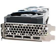
proper airflow. In the same area, we also found
a plethora of connections for I/O devices such as the
memory card readers, game port, COM2 port, as well as
the CD-IN connection and option 6-channel audio port
bracket. It's possible to have at least eight
separate cables all trying to fit in between the back
of the case and the CPU with heatsink. Far too
many connections for just one corner of the board in
our opinion.
There are only 2 DIMM
slots, each supporting up to 1GB of DDR200 or DDR266, which meets
the official specifications of the i845 chipset.
In each corner, there was one 3-pin fan header,
although I prefer including at least three - the more
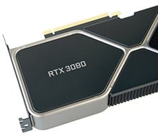
the merrier. One feature that I liked was the
sliding lock mechanism used to keep the AGP card in
the slot securely. While some boards have a
simple lever (and some have nothing at all), the IWILL
P4ES has a brace around the AGP slot. After
inserting the AGP card, one slides the brace forward,
locking the card into place. I think that this
is the best method of preventing the card from
creeping out that we have seen.
The floppy drive connector
is placed along the edge of the board, close to where
the end of the drive would usually be (in most
enclosures) and allowed us to keep the cable tightly folded
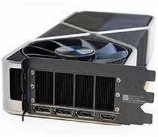
and out of the way. The IDE ports are placed
along the edge in the other corner, and are out of the
way of all other cables and drives. The only
detriment here is that a number of typical IDE cables
could prevent airflow from a front fan from reaching
the rest of the board. The IDE ports were color
coded, with the closer blue ports being used for ATA
100 drives, and the two yellow ports for ATA 133.
These are controlled by the nearby Promise 20275
controller chip. Unfortunately, the two ATA 133
ports did not have any RAID support, a feature common
on many modern boards. As if 4 IDE ports weren't
enough, as we looked in the final corner of the
board, we found the Silicon Image SATAlink chip with 2
nearby SATA connections. Once the drives are
available, it could be assumed that the aspiring
"do-it-yourself" upgrader would eschew the ATA 133
ports for a serial connection. This editor,
for one, can't want to get his hands on a SATA drive
and give it a ride.
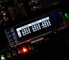
THE BIOS:
The BIOS was made of your typical
fare from AWARD. You can check the Standard CMOS
features for changing the system clock, and check
on what drives are identified on the IDE channels.
Going to the Advanced CMOS features, you can make sure
that the CPU cache is enabled, and determine the boot
order. If you have the bootable hard drive on
the ATA133 or SATA channels, make sure to choose the
correct setting in Onboard Devices Load Order as shown
here. Next, in the Advanced Chipset Features, you have
options to change the DRAM settings. I set up my
stick of Corsair PC3000 DDR using the most aggressive
timings, but was limited to using to using a DDR 200
or 266. Even though DDR333 is not officially
supported in the i845E specs, it would have been nice
to unofficially allow for this. As of this
release of this article, the i845PE and i845GE have just been
released, which will fully support DDR333.
There weren't too many
options to use when we got to overclocking the P4ES,
although this did not seem to hinder my progress too
much. On the IWILL Smart Setting screen, your
only options are to enable or disable Spread Spectrum,
raise the CPU clock by 1MHz intervals, enable or
disable the ATA133 and SATA connectors, and step up
the CPU Voltage. You can also disable or enable the standard IDE
ports, on-board audio, etc., and check on the
voltages and fan speed on the PC Health screen.
|